
Lesson 2
The course of practical work
Step 1. Now we are assembling the details of the manual model printed on a 3D printer. First, adjust the parts as shown in Figure 17.
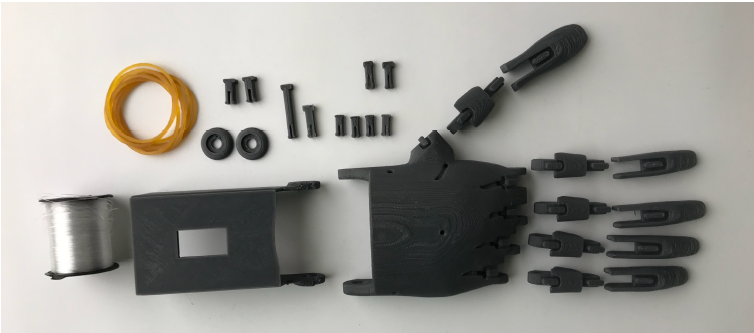
Fig.17. Details of the right hand model
Step 2. Let’s start from the beginning by collecting the palm and forearm. We fix the bolt and washer through the hole at the junction of the palm and wrist, similar to the nail in the upper part of the arm model, as shown in Figure 17. An example of a specific set is shown in Figure 17.
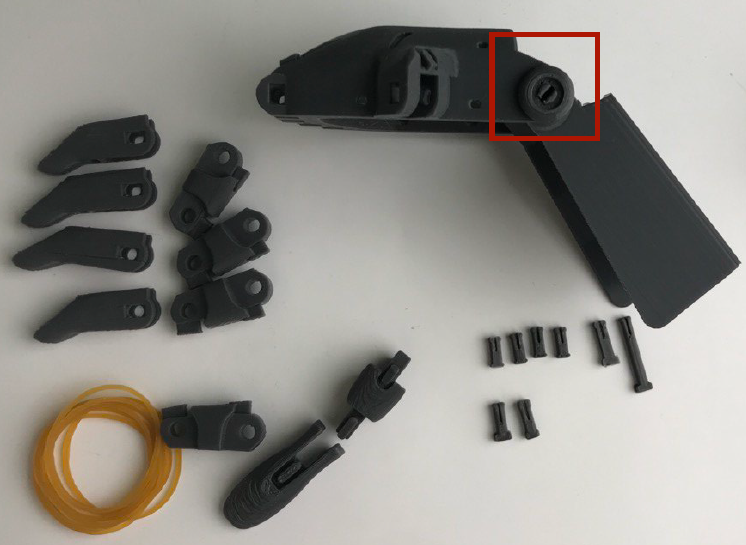
Fig.17. Merging of palm and hand
Step 3. Assemble the fingers using exactly such bolts. We collect all the fingers as shown in Figure 18. The two long fingers 4, shown in Figure 17 on the left, are the index and middle fingers.
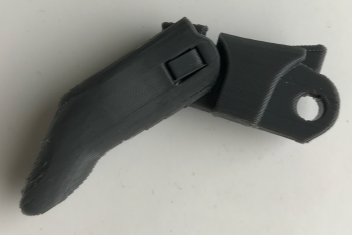
Fig.18. Finger collection scheme
Step 4.combine the collected fingers into the palm of your hand. We attach the front thumb to the side of the palm, and the index finger and middle finger are fixed with the longest Bolt,and the other two fingers are fixed sequentially, separately, with bolts.
Step 5. Now, to simulate the antagonist muscles on the outside of the fingers, connect the bumps outside the finger with an elastic band.
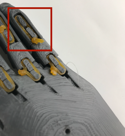
Fig. 19. The antagonist of the “gum” on the fingers
Step 6. And the agonist attach the muscles to the finger with a rod (fishing line) and transfer from the holes under the fingers outside the palm. After passing the palm over the brush, we remove all the finger threads from the brush by 10 cm in excess.
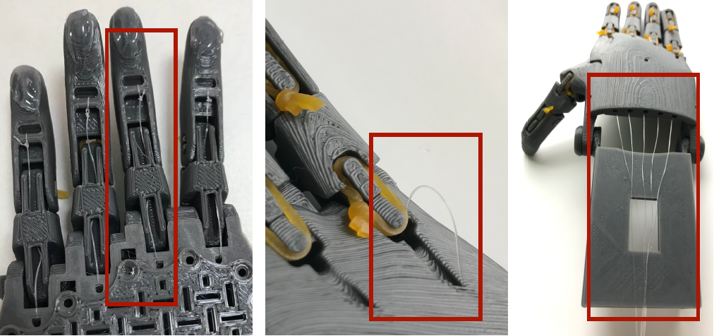
Fig. 20. Agonistic “elastic bands” on the fingers and their ligaments
Step 7. Now we install the servo motor, which we attach to the hole in the lowest part of the model using an elastic band from under the bracelet. On the white handle of the same servo motor, we need to tie the strings of the rod. First, bending our fingers, we tie the rods sticking out of it to the servo motor.
Fig. 21. Servomotor and bait threads
Step 8. The control button 1 bends and locks the fingers through the servo motor. To do this, the electrical circuit is assembled as shown in Figure 22, and is given at the
Code
#include <Servo.h>
Servo myservo;
#define CTS1Pin 2 // Pin for capactitive touch sensor 1
#define CTS2Pin 3 // Pin for capactitive touch sensor 2
int pos;
void setup()
{
   myservo.attach(9);  // attaches the servo on pin 9 to the servo object
}
void loop()
{
int CTSValue1 = digitalRead(CTS1Pin);
int CTSValue2 = digitalRead(CTS2Pin);
if (CTSValue1 == HIGH)
 {
    for (pos = 0; pos <= 180; pos += 1)
    myservo.write(pos);
     delay(15);
   }
   if(CTSValue2==HIGH)
   {
    for (pos = 180; pos >= 0; pos -= 1)
    myservo.write(pos);
    delay(15);
   }
The ARDUINO code is being written.
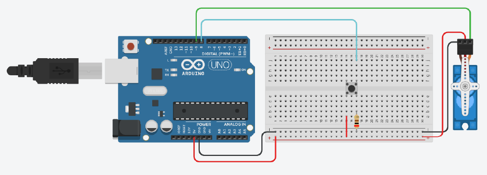
Fig. 22. The chain required for flexion and extension of the fingers