
Lesson 3
The main parts of the wind generator
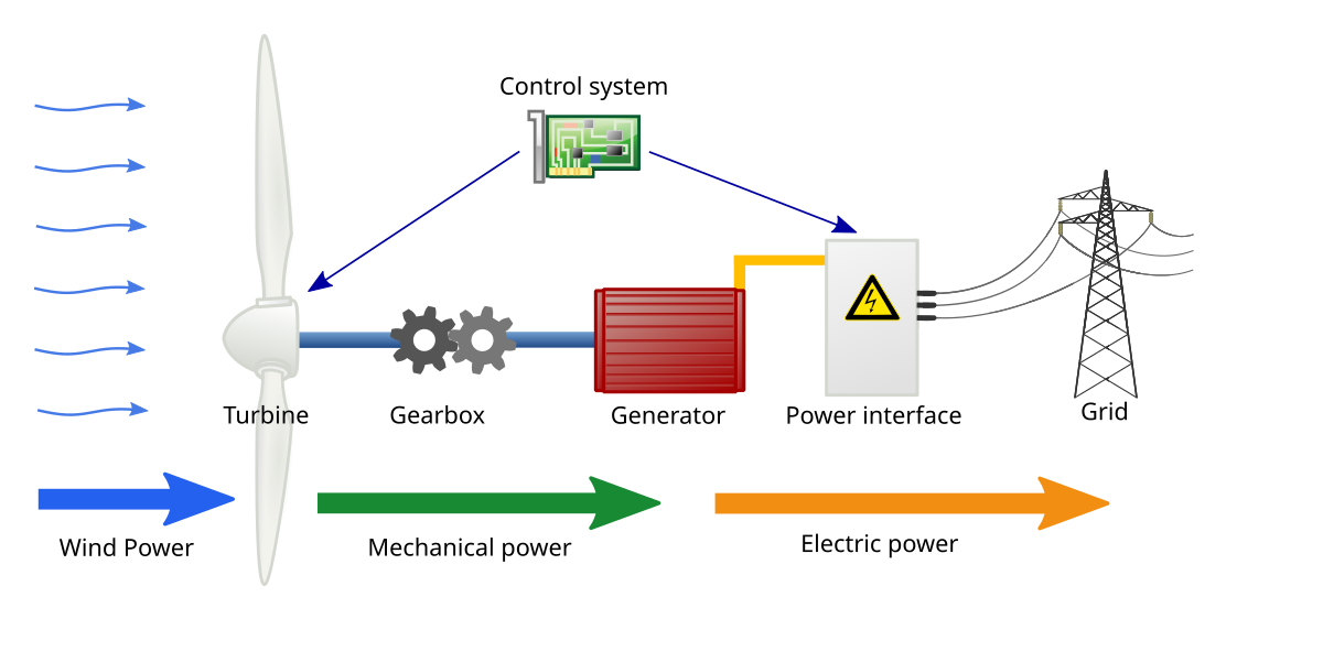
The wind turbine consists of:
Wind turbines mounted on a mast with extensions and untwisted by a rotor or blades;
The received electric power is supplied to the electric generator:
Battery charge controller connected to batteries (usually 24 V)
Inverter (= 24 V -> ~ 220 V 50Hz) connected to the mains
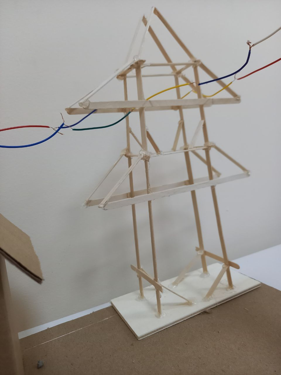
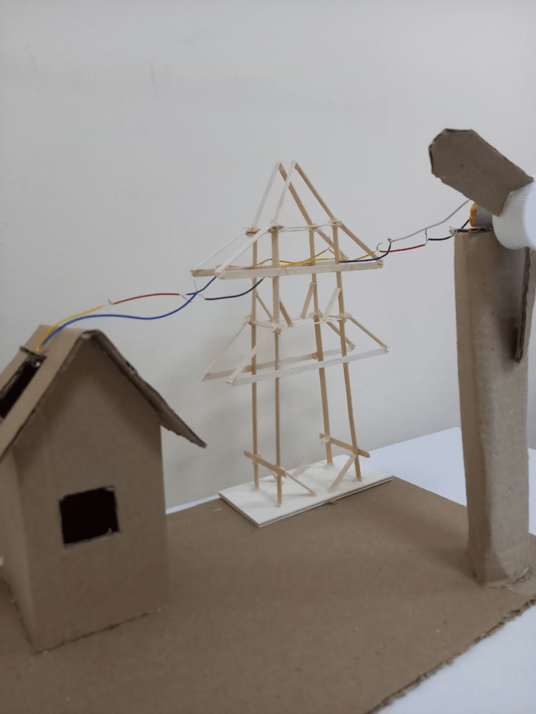
Industrial Wind Farm

It consists of the following parts:
Foundation
Power cabinet including power contactors and control circuits
Tower
Ladder
Rotary mechanism
Gondola
Electric generator
Wind direction and speed tracking system (anemometer)
Brake system
Transmission
Blades (usually three, since rotors with two blades are subjected to heavy loads at a time when a pair of blades is vertical, and more than three blades create excessive air resistance)
The system of changing the angle of attack of the blade
Fairing
Fire extinguishing system
Telecommunication system for transmitting data on the operation of a wind turbine
Lightning protection system
Pitch Drive
Low-power wind generator model
It consists of the following parts:
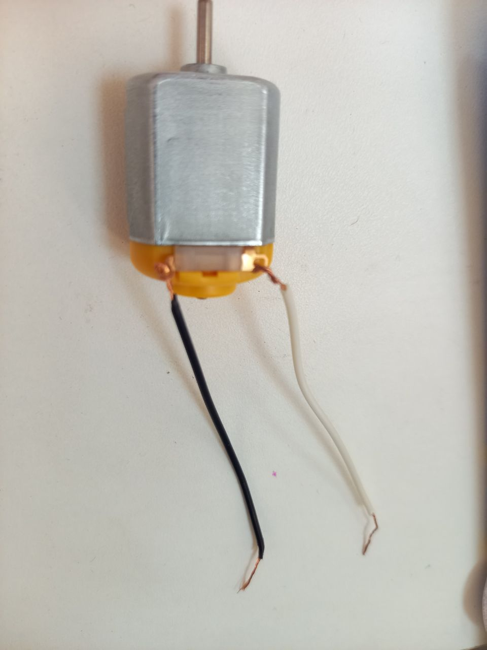
Small DC electric motor (3-12 V) (used as a generator)
Silicon Rectifier Diode
Electrolytic capacitor (1000 UF 6 V)
The practical part of the work
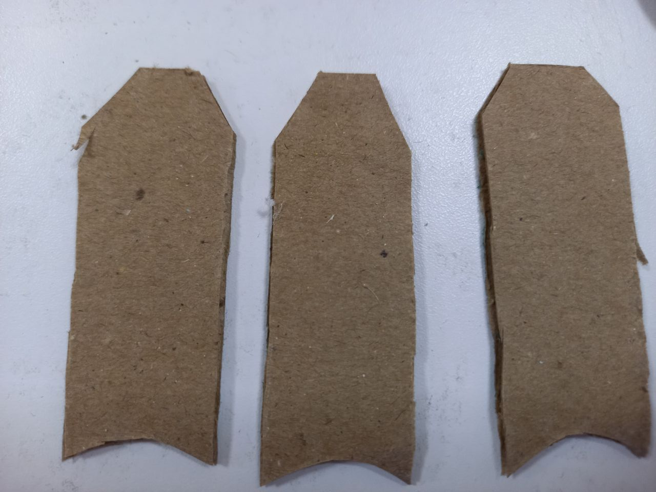
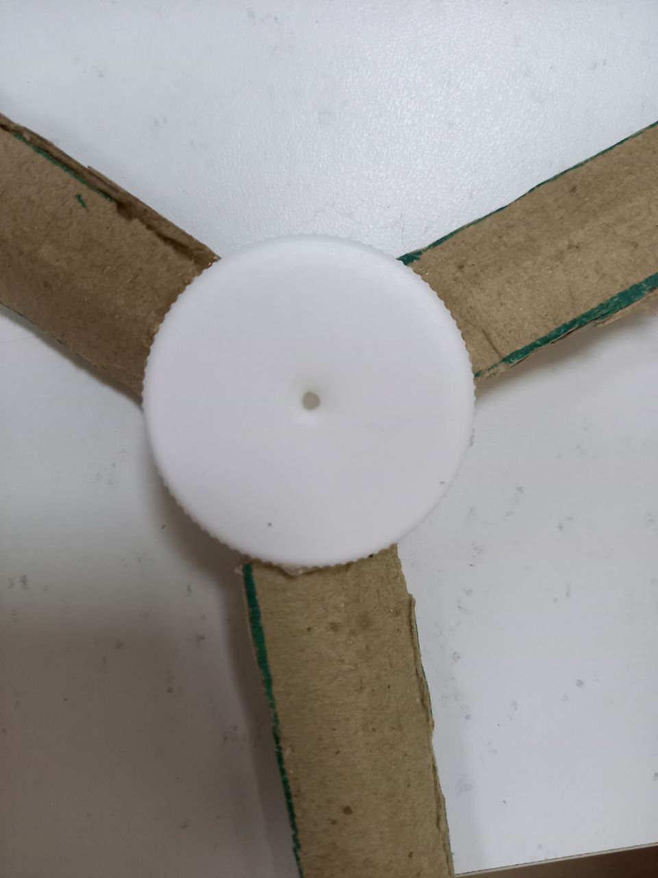
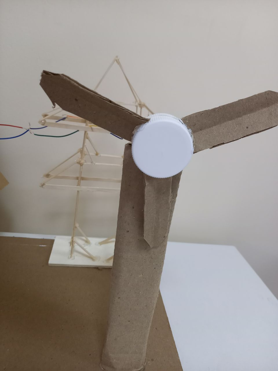
Step 1. First of all, we make the blades of the wind generator. To do this, we take cardboard and cut out 3 blades in the same way according to the drawing. Blade length – 8 cm, width – 3 cm.
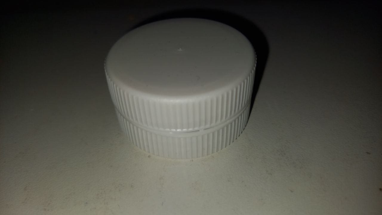
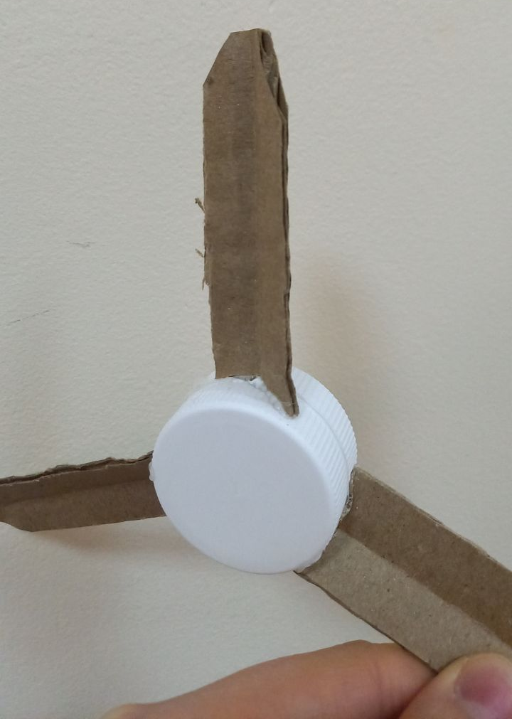
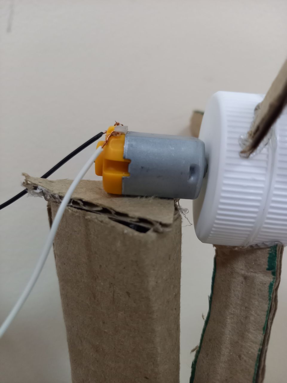
Step 2. Take 2 covers and connect them with hot glue. Then we glue our cardboard blades on the lid, in a rounded form
(Since the operation of the wind turbine is based on the maximum use of an alternative energy source, one side of the blades has a rounded shape, the second is relatively flat. When the air flow passes along the rounded side, a vacuum section is created. This sucks in the blade, taking it to the side. At the same time, energy is created, which causes the blades to spin.)
Step 3. On one of the covers we make a hole with the size of the motor shaft
Step 4. Take 2 wires and connect them to the motor
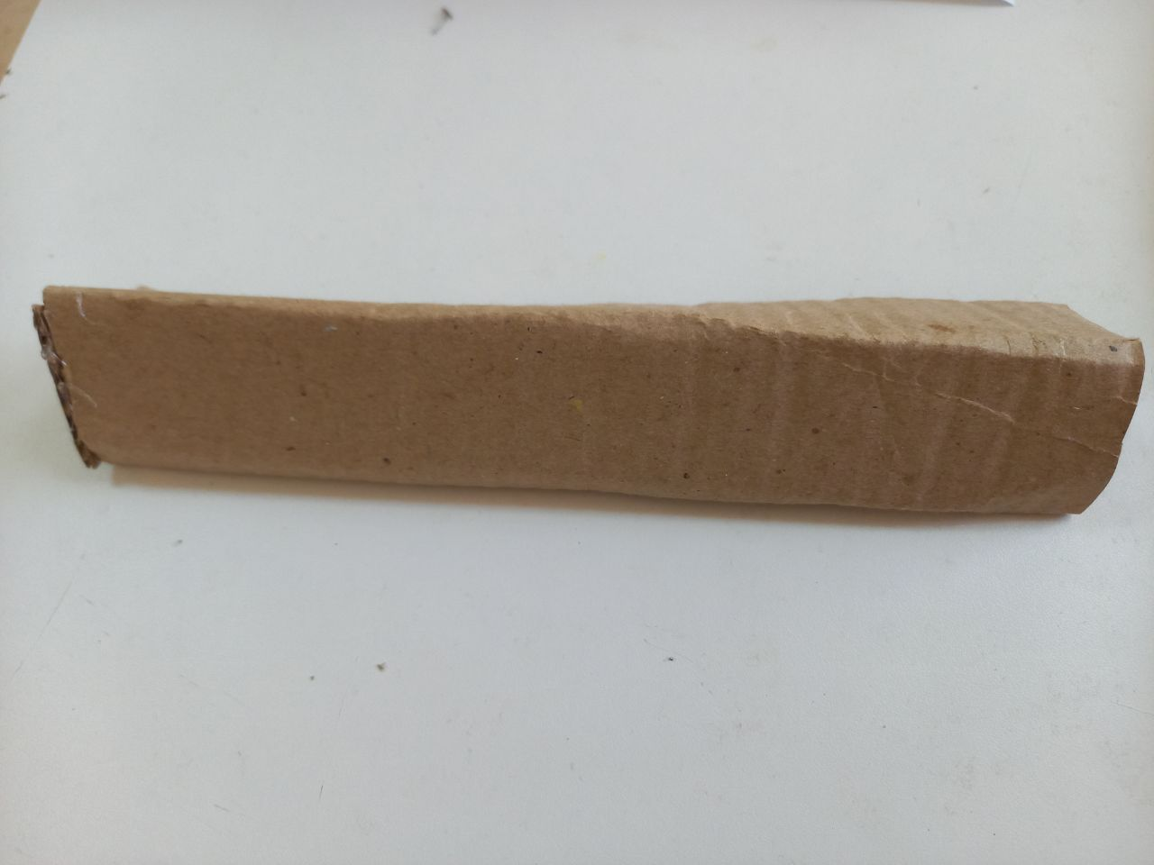
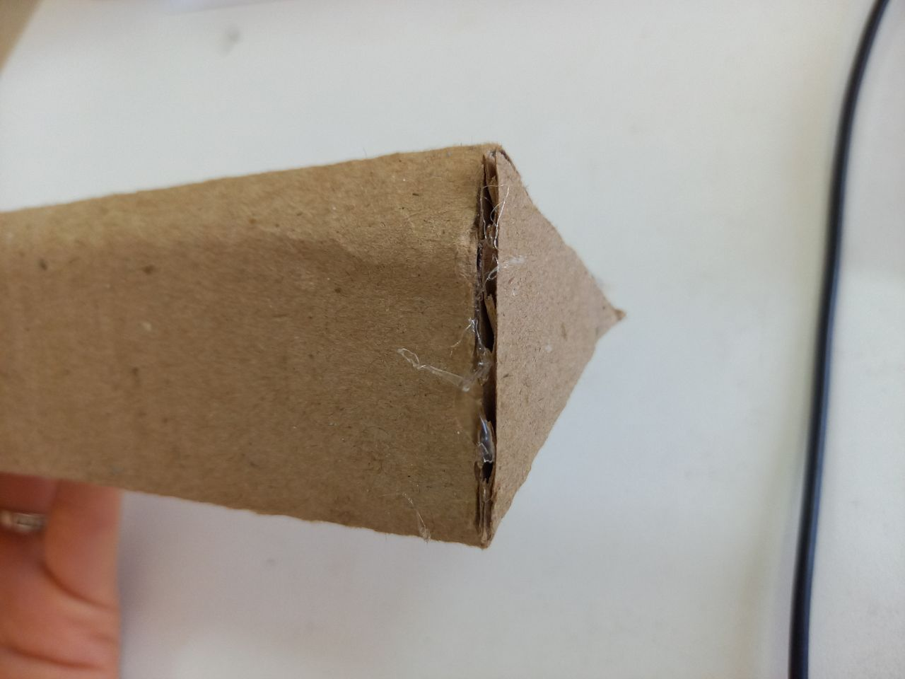
Step 5. Now we will make a tower out of cardboard, take a cardboard with a size of 22×12.5 cm, cut it out and twist it in the form of a triangular tube
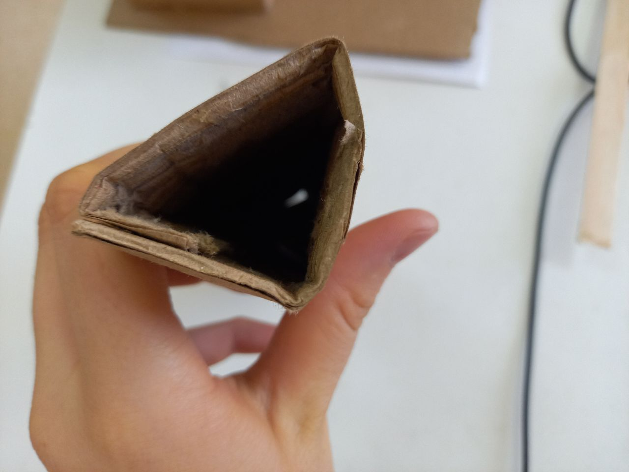
Step 6. We also cut out a triangle from cardboard and glue it to the surface of our tower. We attach an engine with a fan to the surface of the tower .
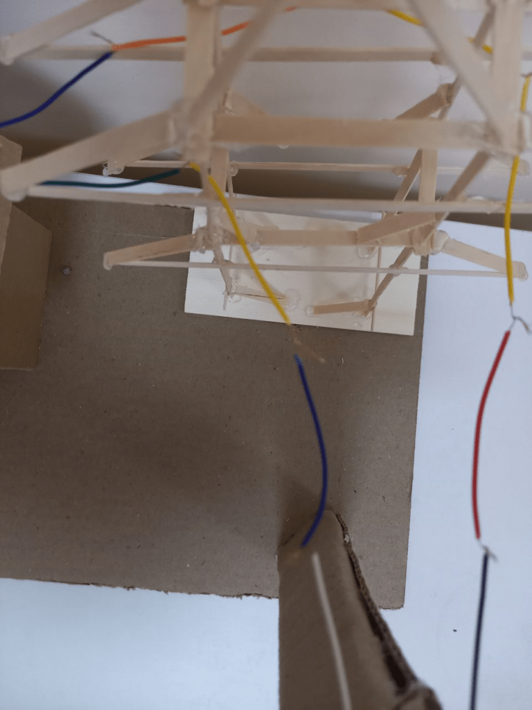
Step 7. All ready-made layouts are fixed on a cardboard base with a size of 33×24 cm
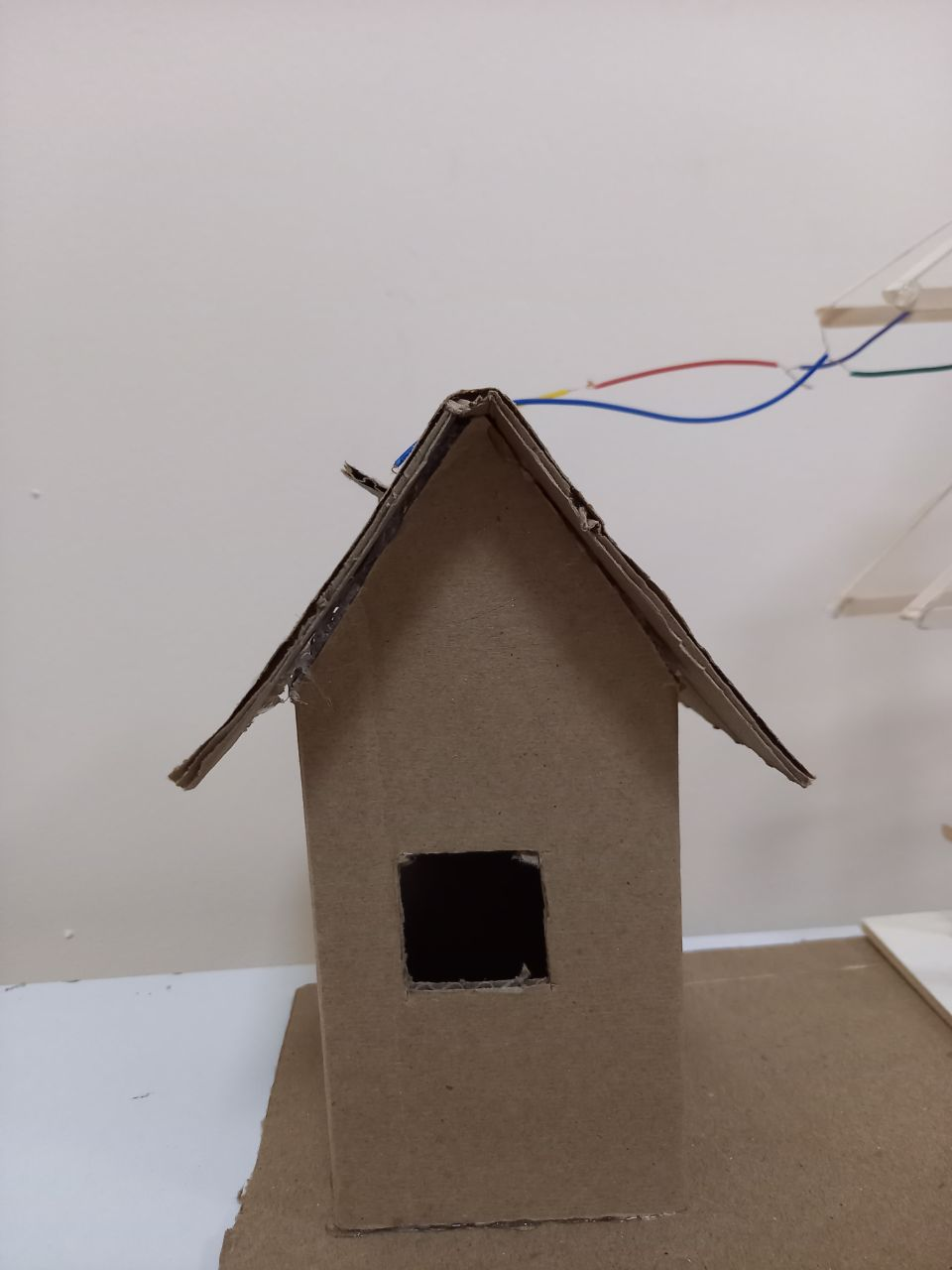
Step 8. Now we connect all the wires so that the current passes through them
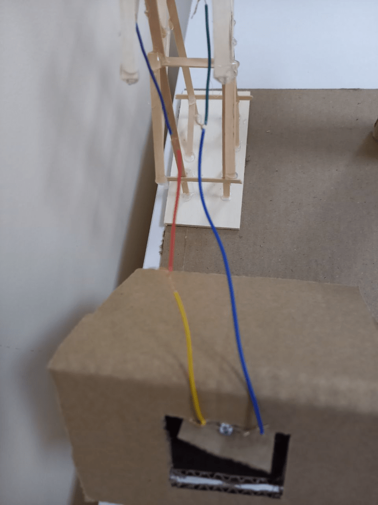
Step 9. As soon as we have finished connecting the wires, only at the end we connect the battery compartment c between the two wires as shown in the figure
It’s important to know!
Each charge has a “+” and “- ” . A new LED, as a rule, has two outputs (legs), one of which is slightly longer than the other. The long lead is the anode (+). The short output is the cathode (–). Touching the anode to the plus, and the cathode to the minus, a serviceable emitting diode will glow. At the battery compartment (+) is the red wire, and (-) is the black wire. Therefore, the long leg of the LED must be connected to the red wire of the battery compartment, and the short leg to the black wire of the battery compartment.