Lesson 3

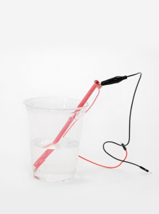
Creating a sensor to determine the electrical conductivity of water

In this lesson students:

  • create a water conductivity sensor
  • assemble a sensor connection diagram
  • connect sensors to the board
  • write a program to display

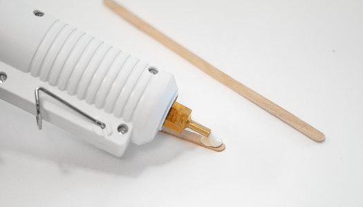
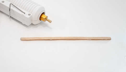
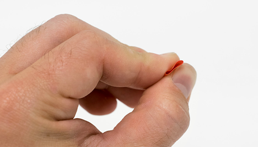
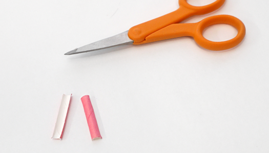
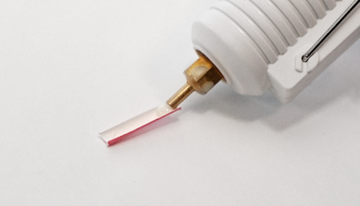
Assembly instructions

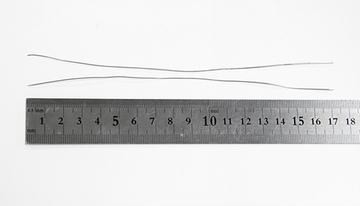
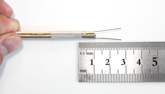
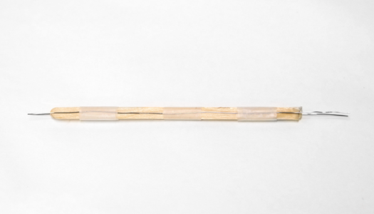
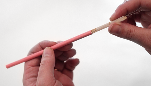
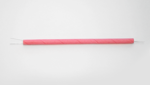
Let’s create a sensor to determine the electrical conductivity of water

1 | Mark the straw at a height of 14 cm.
2 | Cut the straw at the 14cm mark, using the inside of the scissors to prevent the straw from cracking. Set both pieces aside.
3 | Then mark the 13cm mark on the coffee stir stick.
 
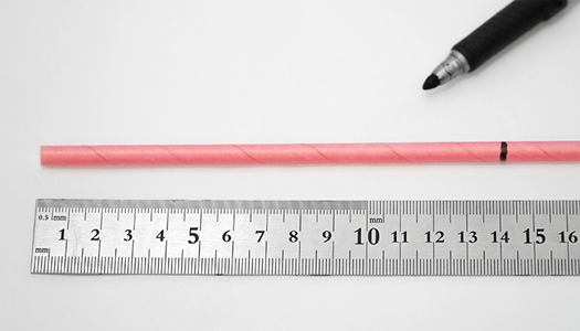
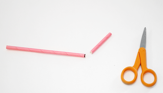
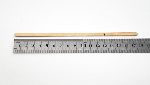
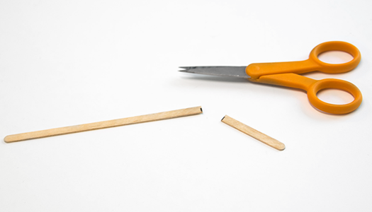
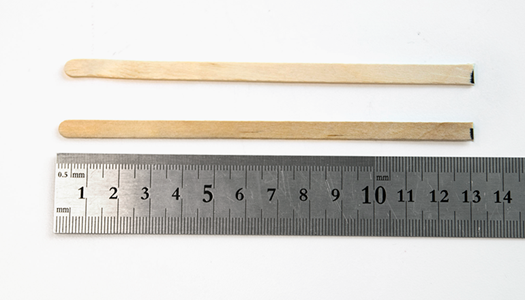
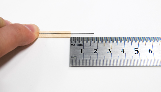
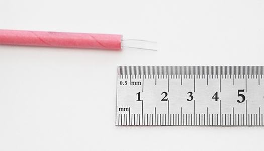
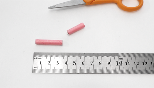
4 | Cut the stir stick at the 13cm mark
5 | Repeat steps 3 and 4 to create a second stick that is 13cm long.
6 | Using a glue gun, apply a thin line of glue along one of the stir sticks
7 | Quickly press the sticks together until the glue cools.
8 | Measure and cut two pieces of stainless steel wire 17 cm long. Align the wires as best as possible.
9 | Center the stainless steel wire on the stir stick and 1.75 cm from the end of the stick.
10 | Center the other wire opposite the first. Attach the wires to the stir sticks.
11 | Wrap the middle and opposite ends of the sticks with tape to hold the wire in place, keeping the wires centered on the sticks.
12 | Insert wire stir sticks into a 14cm straw.
13 | Measure to make sure your wires are sticking out the end of the straw at the 1.5cm mark.
14 | Make sure your sensor looks like the photo above.
15 | Apply some hot glue to the end of the straw where your wires stick out about 1cm.
16 | Then glue the other end of the straw to completely seal the inside of the straw and let dry.
17 | Measure and cut the remaining straw to 4cm length.
18 | Squeeze a 4cm long straw until it is flat.
19 | Cut the straw along the folds created by pinching the straw.
20 | Apply hot glue to the inside and one end of the 3cm straw.
21 | Quickly place the sensor on the straw guard with the guard sticking out just beyond the ends of the wire.
22 | Bend the longer ends of the wire as shown in the photo above. This gives the alligator clips a better connection once attached.
23 | Bend the longer ends of the wire as shown in the photo above. This gives the alligator clips a better connection once attached.
24 | Great! You are now done with the EC sensor. Now you are ready to connect to your microcontroller.

You can start from the listener level and suggest connecting sensors to the board without a ready-made template

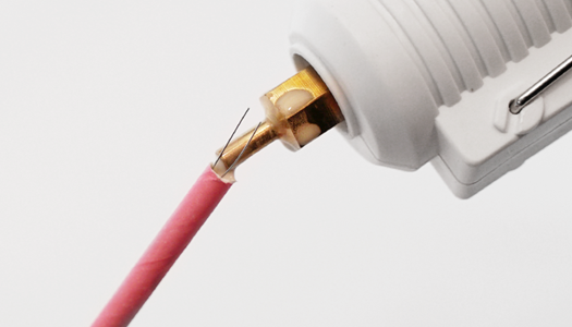
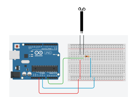
We connect the sensor to the Arduino board

  • one contact, using a 10K resistor, is connected to the negative GND
  • We also connect this contact to the analog pin
  • connect the second contact to positive +5V

It is also necessary to write a program to display data from sensors

You must use a port monitor to output data

void setup() {

  Serial.begin( 9600 );

  pinMode( A0, INPUT );

}

void loop() {

    ecMeterReading = analogRead( A0 );       

    ecMeterVoltage = ecMeterReading * 5.0;

    ecMeterVoltage = ecMeterVoltage / 1024;                           

    delay(250);

  Serial.print( ecMeterVoltage , 4 );

  Serial.print( "," );

  Serial.println();

}