Lesson 3
Smart lighting
Before the lesson begins, assemble the diagram from the last lesson so that the garage is complete. Two circuits will be assembled on one breadboard.
In this lesson, we will make smart lighting with a motion sensor. To do this, you need to add a PIR motion sensor to the circuit. It allows the device to work in automatic mode. Depending on the presence of movement on the premises, the device will turn on and off light. When the motion sensor is triggered, a voltage is applied and the LED lights up.
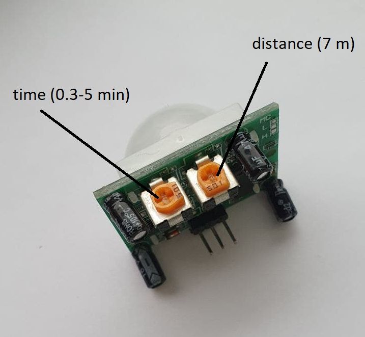
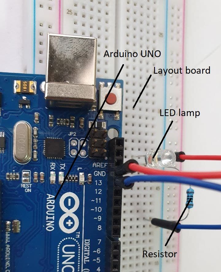
The next step will be to assemble a system for automatically turning on the light. It will consist of a circuit with a motion sensor, an LED, an Arduino UNO board, and a 100-ohm resistor.
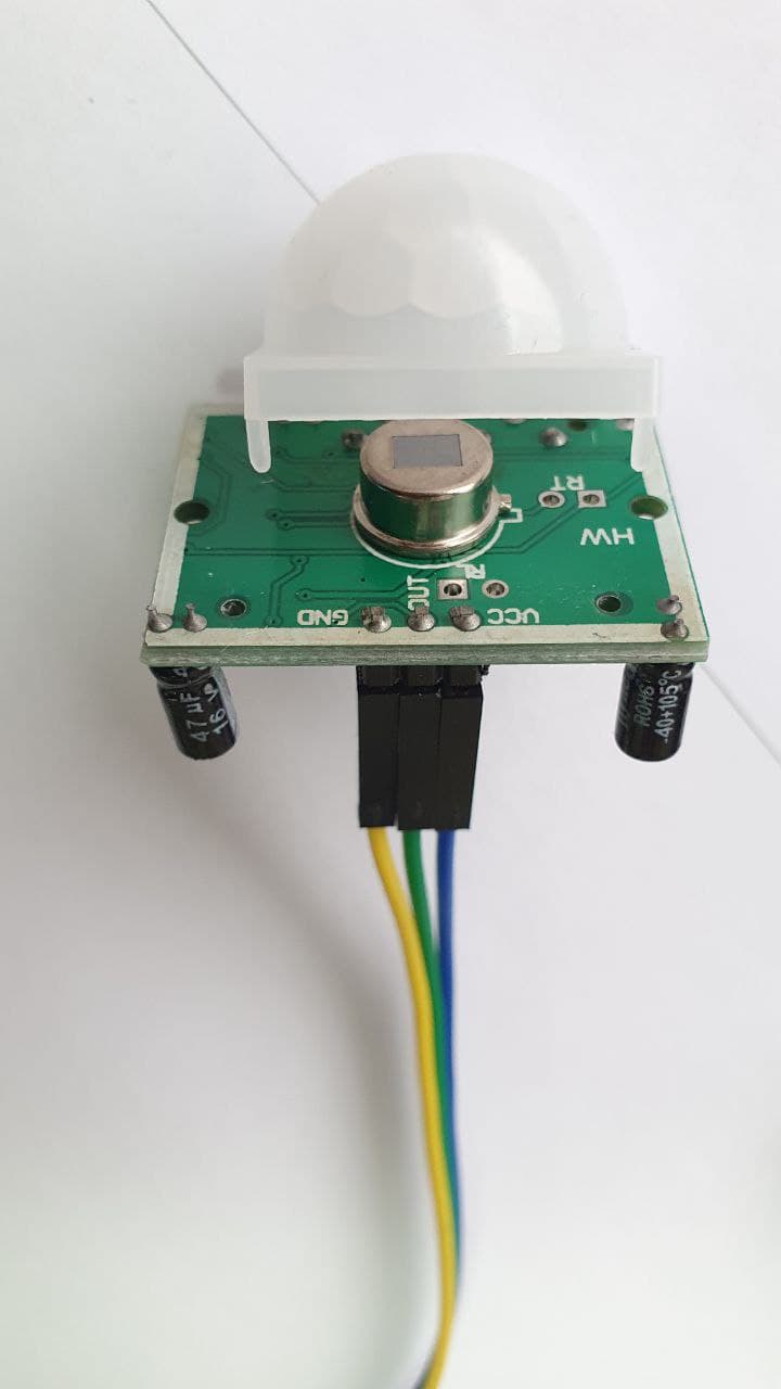
Assembling the layout. We bring the wires exactly as in the picture.
1. From Arduino to sensor: GND → GND; 3 → OUTPUT; 5V → UCC.
2. On the breadboard: We put the LED on the breadboard. The short contact of the LED is connected to the Arduino GND (we conduct a wire from the row on which there is a short contact of the LED to the Arduino GND). We conduct a long contact of the LED to the resistor (we put it on one row on the breadboard). The other end of the resistor is connected to Pin13 (13) on the Arduino.
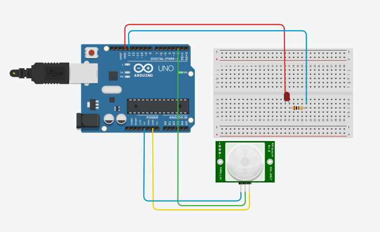
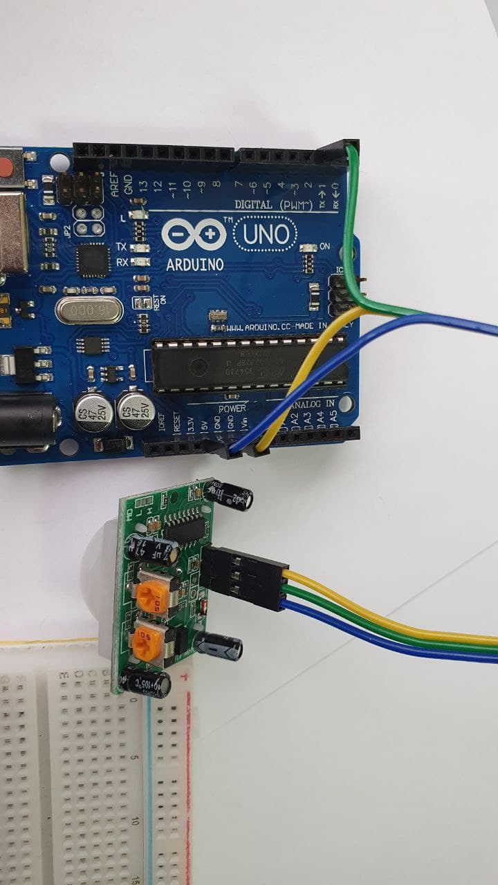
The finished circuit of the Arduino, breadboard, and motion sensor looks like this.
- Connect the Arduino to the computer via USB.
- Now we will write a program that will turn on the LED when the sensor is triggered. Next, open the Arduino IDE program, copy the code below and paste it.
#include <IRremote.h> // connecting the library
#include <Stepper.h> // library for stepper motor
#define pirPin 3
#define ledPin 13
int RECV_PIN = 2; // we connect the signal pin to the 8th digit.conclusion
IRrecv irrecv(RECV_PIN);
decode_results results;

const int stepsPerRevolution = 40; // the number of steps per 1 revolution, change the value for your motor
Stepper myStepper(stepsPerRevolution, 8, 10, 9, 11);


void setup()
{
  Serial.begin(9600); // open serial
  myStepper.setSpeed(130); // we set the speed to 130 rpm
  irrecv.enableIRIn(); // initialization of the IR receiver

  pinMode(pirPin, INPUT);
  pinMode(ledPin, OUTPUT);
}

void loop()
{
  delay(500);
  if (irrecv.decode(&results)) {


    if(results.value==16769055) {
      myStepper.step(1700); // We take 1500 steps in one direction

      Serial.println("tusti");}
    else if(results.value==16754775) {
      myStepper.step(-1700); // We take 1500 steps in the other direction
      Serial.println("koterildi");
    }


    Serial.println(results.value, DEC); // output in the 16th mode
    Serial.println(); // for convenience, add an empty string
    irrecv.resume(); // we get the following value
  }

  int pirVal = digitalRead(pirPin);
  if (pirVal == HIGH)
  {
    digitalWrite(ledPin, HIGH);
    Serial.println("Есть движение");
    delay(2000);
  }
  else
  {
    Serial.println("Нет движения");
    digitalWrite(ledPin, LOW);
  }
}
- Check and upload the code to the Arduino as in the last lesson and check the operation of the sensor. You can twist the sensor settings and see how this will affect its operation.
- We will install lighting inside the garage. Done, now when the owner comes home, the garage opens with a remote control and when he enters the garage, the light turns on automatically.
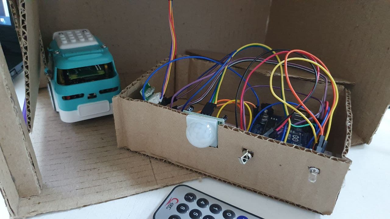
You can make housing for sensor circuits.
Think about whether it is possible to install such a motion sensor at your home or in the garage. In which rooms, rooms at your home could this be done? How often do you leave the light on and could you save on electricity with such an arrangement? You can discuss this with your parents. And for the next lesson, prepare some such examples. Explain why exactly in one place or another you would install such a sensor.
And if such a sensor could be installed not only on lighting? Offer your ideas.
Conclusion
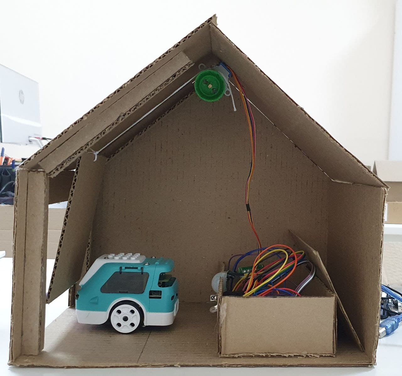
In this project, we have made a functioning smart garage, which consists of smart lighting and smart gates. The students made a garage with their own hands, this contributes to the development of design skills and creative thinking, skills of working with electronics and Arduino.
Demonstration
The result will be a working layout of a smart garage.
– Students should present, show and tell how they designed the garage, what materials they used and what they learned during the work.
– What ideas did the students have after working on the project?
– What other technologies can be implemented in a smart garage?
– What advantages does a smart home have over an ordinary house (what disadvantages)?
– What functions of a smart home, garage are missing in everyday life?
Evaluation
PBL based assessment criteria:
Problem-based learning is a teaching method in which students acquire knowledge and skills, working on one project for 4 weeks, to research and find an answer to a genuine, interesting and complex question, problem or challenge. (follow the link)
For project grading, in the first week, provide this material (PBL rubrics) to students in order to:
– the students previously understood by what criteria they need to prepare,
– pupils were able to independently assess their colleagues.